
Compact receiver housing
The supplied front view shows the compact housing and its physical form without adding or changing product details.

<!doctype html>
A compact wired receiver for compatible wireless room-control applications.
The TELIN RF Receiver is presented here using the supplied product photography exactly as provided. The product views show the housing, terminal openings, ventilation structure and wiring reference without changing the product geometry or visible markings.
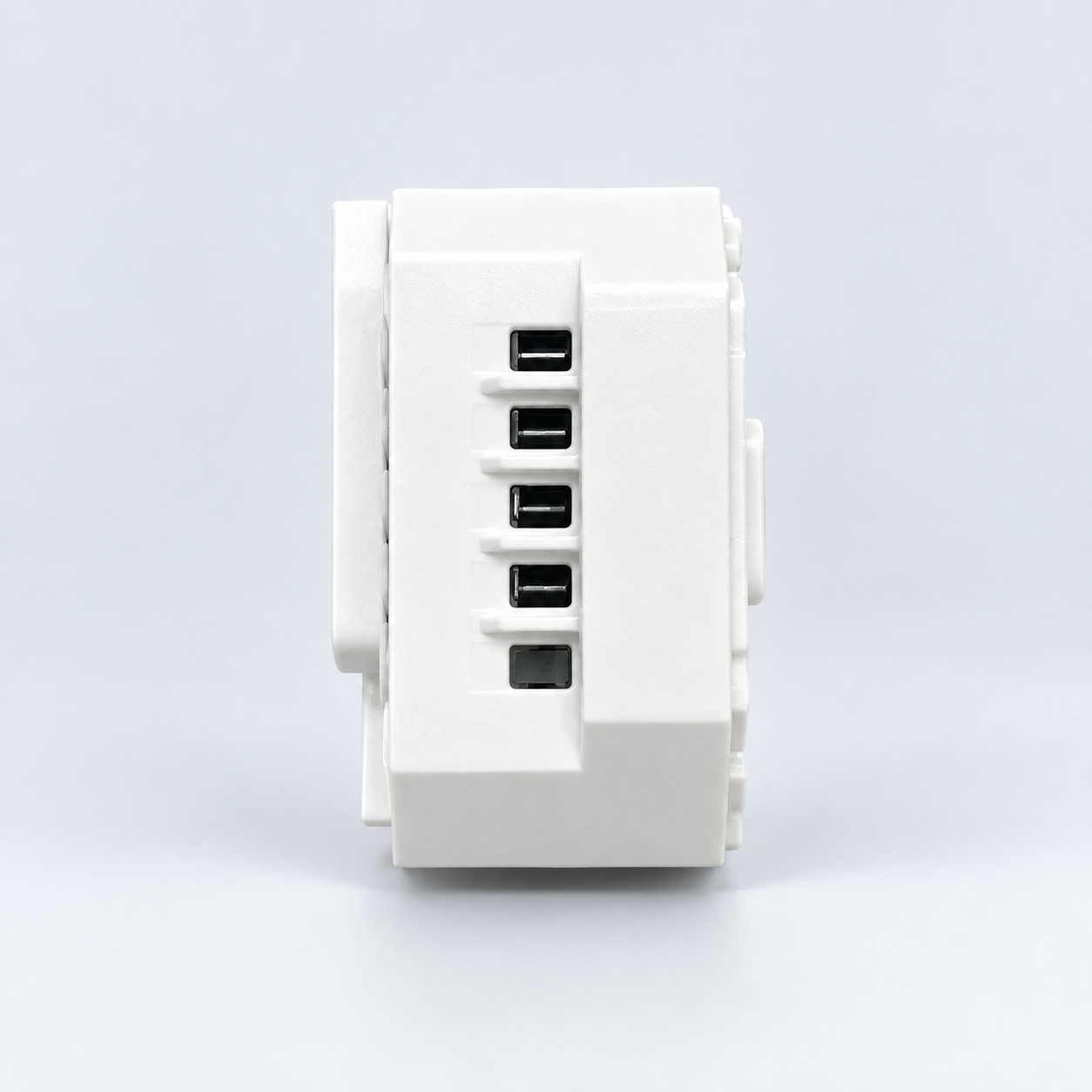
The supplied documentation describes a wireless room-control system in which room temperature is detected by an NTC sensor and the connected heating or cooling equipment is automatically switched to maintain the desired temperature. The receiver is the wired switching component shown in the supplied product photography.
The supplied front view shows the compact housing and its physical form without adding or changing product details.
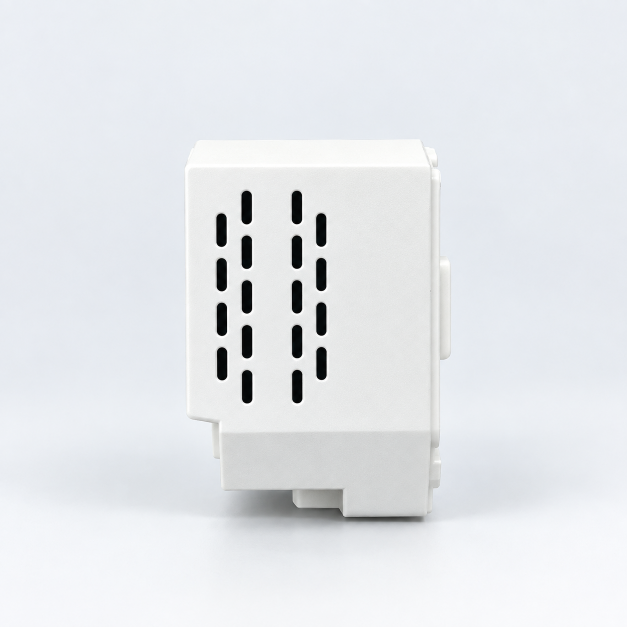
Ventilation openings are visibly integrated into the housing and are retained exactly as shown in the supplied image.
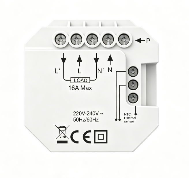
The supplied wiring image shows P, L′, L, N′, N, LOAD and the external NTC sensor connection, with a visible 16A Max. marking.
Electrical values and visible markings should be confirmed against the final technical datasheet, production configuration and local electrical requirements before ordering.
The supplied product photography shows a compact receiver housing with terminal access, ventilation openings and a dedicated wiring reference. It is presented as the wired switching component within a compatible wireless room-control system.
Final application suitability depends on the connected equipment, electrical installation and production configuration.
These system parameters and functions are retained from the supplied AC8048RF-Plug documentation as system reference. They are not claims that the receiver housing itself contains an LCD, keypad or thermostat sensor.
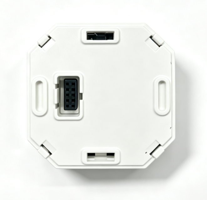
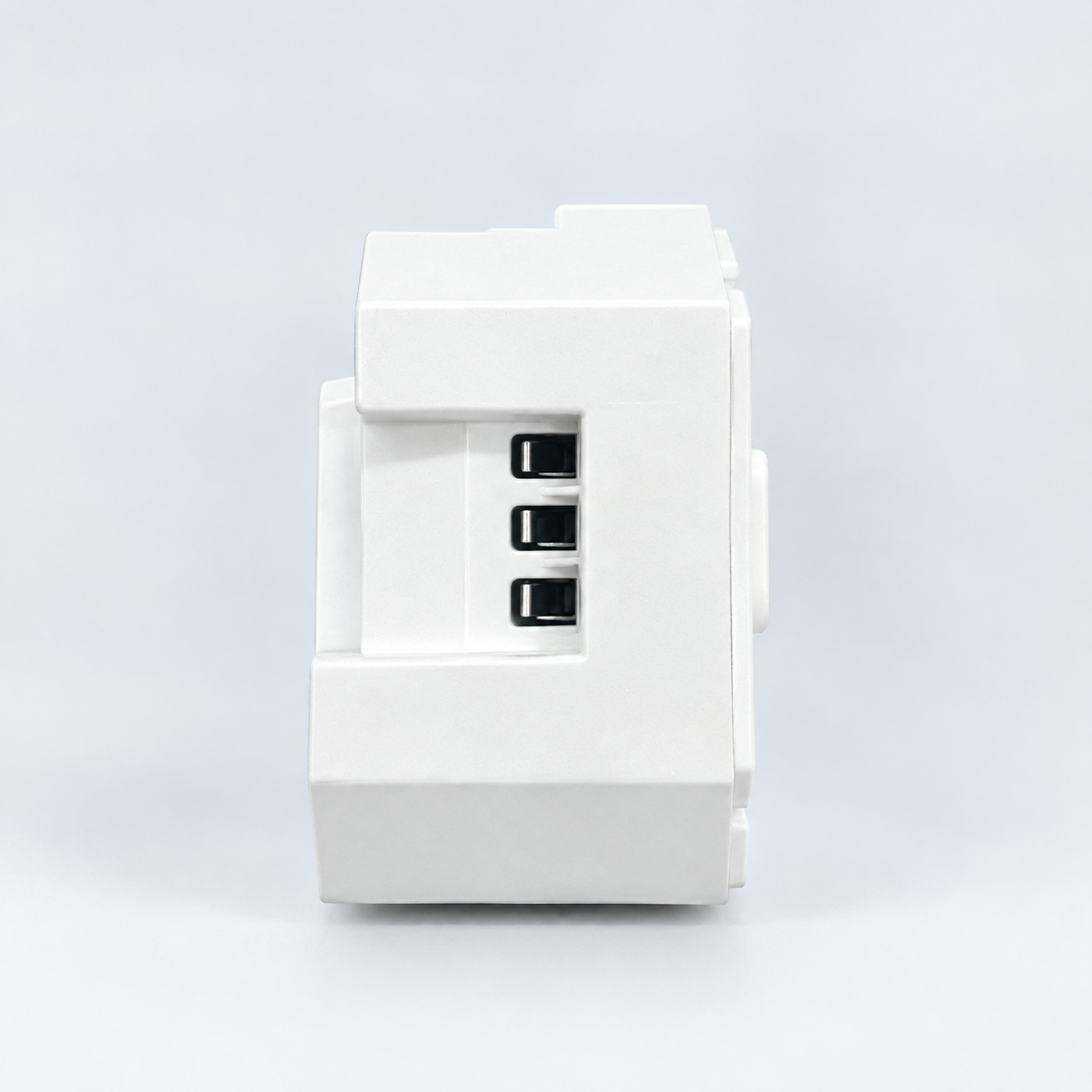
All product visuals on this page are based on the supplied original images. Product geometry, terminals, openings, connectors and visible markings have not been redesigned.
The supplied document describes a code-pairing process in which the receiver enters pairing state and waits for the transmitter / thermostat to complete the address-code procedure.
Final wiring, connected load, RF frequency and installation method should be confirmed against the production configuration and applicable local electrical requirements.
Share your application, load, RF frequency, sensor and quantity requirements so the receiver configuration can be confirmed before production.
 Optimized by Seraphinite Accelerator