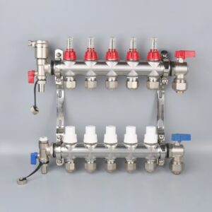


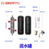
Product Overview
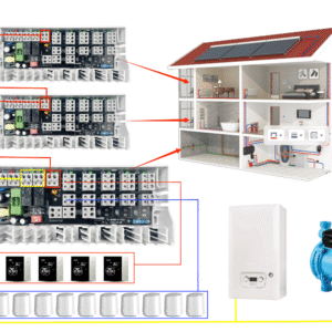
The Hydraulic Coupling Tank is designed to hydraulically separate the primary and secondary
circulation systems in HVAC and heating applications.
It ensures stable flow, balanced system operation, and reliable boiler protection,
especially for wall-hung gas boilers and heat pump systems.
Description
Functions & Benefits
- Hydraulic Decoupling:
Allows the primary and secondary circulation systems to operate independently.
Each loop flow rate depends only on its own pump, eliminating mutual interference
caused by pump interaction. - Flow & Power Balance:
Maintains the required flow rate and velocity in the primary system.
This is especially important for gas wall-hung boilers to ensure operation
under rated working conditions and to prevent frequent start-stop cycles,
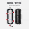
reducing energy waste and extending boiler life. - Multi-function Design:
Integrates air venting, drainage, and water mixing functions to improve
overall system efficiency and stability.
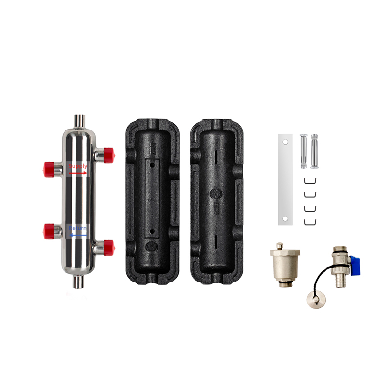
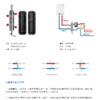
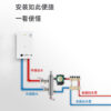
Installation Instructions
- Install strictly according to the supply and return flow directions.
(Red: supply water, Blue: return water) - The 1/2” internal thread ports are used only for automatic air vent
and drain valve connections. They must not be used for branch piping.
(Automatic air vent must be installed vertically.) - Equipped with a wall-mounting bracket for easy installation.
- Supplied with an insulation shell to provide excellent thermal insulation
and reduce heat loss. Do not damage the insulation during installation.
Important Notes
The coupling tank should be installed in locations such as bathrooms, kitchens,
or utility rooms where floor drainage is available.
This ensures safe water discharge during commissioning, maintenance,
leakage handling, or cleaning.
Before system operation, pressure testing must be carried out after installation.
Test pressure: 10 MPa.
Ensure that all connection points are leak-free.
Failure to perform pressure testing according to specifications may result
in quality issues for which no responsibility will be assumed.
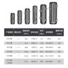
Technical Specifications
| Model | Connection | Flow Rate | Volume (ml) | Recommended Area (㎡) | Tank Diameter | Weight (kg) |
|---|---|---|---|---|---|---|
| DN20 | 3/4” | 2700 L/h | 747 | 50–150 | Ø63 | 1.62 |
| DN25 | 1” | 4800 L/h | 1405 | 100–300 | Ø76 | 2.3 |
| DN32 | 1-1/4” | 7200 L/h | 2673 | 300–400 | Ø89 | 3.43 |
| DN40 | 1-1/2” | 9000 L/h | 3511 | 400–500 | Ø102 | 3.6 |
| DN50 | 2” | 21600 L/h | 6804 | 600–1200 | Ø133 | 5.34 |
| DN25 (2 in / 4 out) | 1” | 6600 L/h | 1899 | 200–600 | Ø76 | 3.1 |